by Howard Sodja, W6SHP
w6shp@amsat.org Article by Howard Sodja, W6SHP. HTML conversion by and feedback to KB5MU.
The following article was originally presented at a Project OSCAR seminar on September 30th, 1990. AMSAT-UK printed an abridged version of this presentation in their OSCAR News, Number 88, April 1991. The original presentation has been reedited and updated for AMSAT’s Web page.
Years of home brewing has taught me how to do and not to do a lot of things properly. This experience, along with reading AMSAT- NA, AMSAT-UK and ARRL publications (Note 1) has taught me how to build my projects better. Here are some tips I learned that may be of help with the most important part of an amateur radio satellite station, the antenna systems.
Low Cost Satellite Antennas
Materials to build satellite antennas can sometimes be found among junk most people would throw away. An old broken-off car radio antenna I found lying in the street became the vertical element of a two meter 5/8 wave groundplane for mode A and T. Four wire clothes hangers became the radials. Likewise all the remaining components were “salvaged” from other junk I had collected here and there. I used this simple matching network:
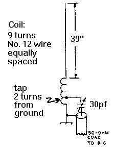
All you need to build a simple VHF or UHF 1/4 wave groundplane antenna is a coax chassis connector and number 12 or larger wire scraps. Solder the vertical element to the center conductor and attach the radials with nuts and bolts to the four corners, then solder each corner. Make the vertical element a bit longer than calculated and bend the radials down 25 to 30 degrees a short distance from the connector flange. Then trim the vertical element (in small increments) for the minimum SWR at the low end of the band in which it will be used. When the SWR begins to go back up, it should be lowest near the center of the band. If not, trim carefully until it is. Then little by little bend the radials down until you get a 1 to 1 SWR. This will be between 30 to 45 degrees, as shown below.
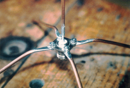
Number 8 wire was used. Ends were hammered flat, filed to shape and drilled. A small propane torch, used carefully so as not to overheat the connector, will make the soldering easy. Flux paste on the connector’s flange will aid solder bonding. The vertical element’s end was filed down until it fit inside the center pin connector. Waterproof the coax connector so water cannot seep into your coax.
Old weathered, corroded junked ham beams are another excellent source of recyclable antenna materials. I salvaged an old phased pair of inoperative Cushcraft two meter beams that were covered with corrosion and rust and were destined for the trash dump. Removing the rusted and corroded hardware was easy after a brisk wire brushing and soaking all the hardware with WD-40 (a penetrating oil) over night. After disassembling all the aluminum elements from the boom, I gave the boom and elements a good soaking and brushing in an acid bath. Acid solutions made specially for cleaning aluminum are available in well-stocked hardware stores. I now had clean looking elements and booms. A little time sanding out the corrosion pits with fine wet sandpaper and the elements and boom were as good as new.
I then drilled pilot holes on one boom 90 degrees and about an inch (2.5 cm) from the existing element holes. Upsizing the pilot holes to the diameter of the elements and securing all the elements with new sheet metal screws one size larger than the original size (so these new screws were tight in the old holes) tied them all together.
For the price of an acid bath and a few stainless steel nuts, bolts and sheet metal screws, a new two meter crossed yagi was born. Do not cut expenses with hardware. Always get stainless steel hardware for structural connections. Brass hardware can be used for electrical connections where there will not be much mechanical stress. The extra expense will be paid back with interest in a few years when it comes time for antenna maintenance.
Likewise I recycled a friend’s junked ancient Hy-Gain trap tribander. After removing all the corroded and rusted hardware and traps and giving the elements a good acid bath, brushing and sanding, I had the makings (for free) for either a 15 or 10 meter beam for modes A, K or T. Essential rusted steel parts, like the boom to element brackets, were wire brushed and painted. As mode A was my objective, this beam came back to life as a full size three element 10 meter beam.
After years of trying various products and techniques to eliminate rust once it is well established, I have found a way that really works. First wire brush the metal with a wire brush wheel attached to either your bench grinder (the best way) or power drill until it is shiny. A base coat of Rust-Oleum ™ Rusty Metal Primer (7769), then a coat of Clean Metal Primer (7773) and two coats of Aluminum Metallic Finish (7715) will keep your paint from blistering and the rust from reappearing for many years. Be sure to use Rust-Oleum thinner as needed to keep the paint at the proper viscosity so it brushes or sprays on properly.
Antenna wire left over from an 80 meter dipole project became the element for my 10 meter horizontal delta loop, which keeps my mode A downlink strong on the overhead portion of my mode A passes. By hanging it only 15 feet (4.5 meters) high with the feed-point near my shack’s window I was able to feed it with a short scrap of coax left over from a 50 foot roll I bought for another antenna project. A quarter wave transformer section of 75 ohm RG-59/U coax from the delta loop’s feed point to my 50 ohm coax feedline was an easy to make match (Note 2).
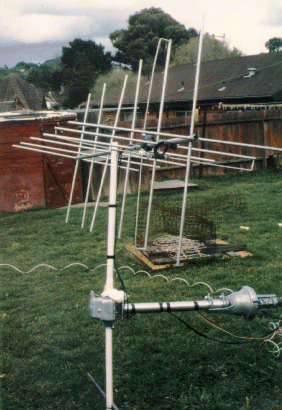
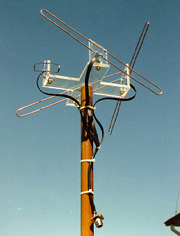
The 70cm Lindenblad antennas I described in AMSAT Journal and OSCAR News articles (Note 3) were built totally from scrap plastic and wire I already had. They were mounted on a pair of old broom handles that I knew I’d have a use for some day, as shown below. This is the best omnidirectional antenna I have ever used as the ability to switch polarizations minimizes QSB and maximizes signal strength.
Antenna Matching
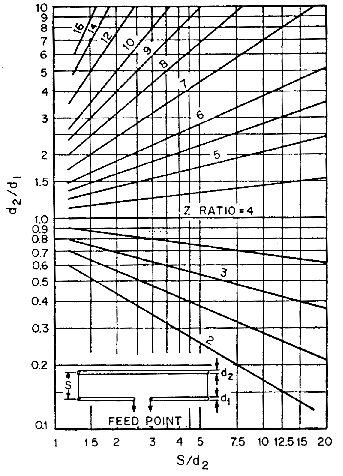
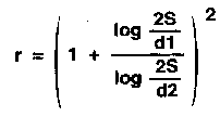
I have had good luck with folded dipole driven elements as they are easy to design and match and have a “flatter” SWR curve than dipoles. The chart below shows the impedance step-up ratio for a two-conductor folded diple, as a function of conductor diameters and spacing. Dimensions d1, d2, and S are shown in the inset drawing. The formula for the step-up ratio, r, is also shown. Besides checking your SWR, check your power output from your matching network, as a bad matching network may give you a good SWR while dissipating RF as heat. I discovered an antenna feedpoint toroid balun that had a power loss I found unacceptable, so I replaced it with one of the lower loss balancing method discussed in the ARRL’s Antenna Handbook (Note 2).
Circular polarized antennas capable of being switched from right to left handed circular polarization will give you the best performance, as polarization can change directions during a pass. The drawing below shows how to do this with 52 ohm antenna feed points. When calculating the length of individual cables be sure to include the velocity factor of the cables.
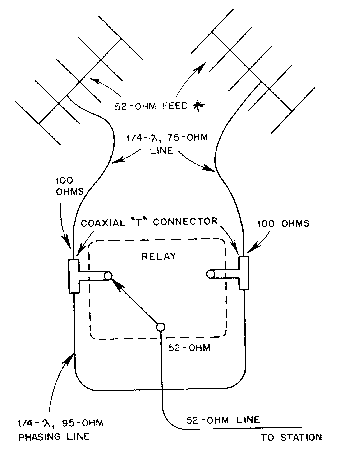
If you use folded dipole driven elements you can modify the design for a 400 ohm feedpoint impedance by using the cabling as shown above, but replace the quarter wave of 75 ohm coax from the coaxial “T” connectors to the dipoles with two eqaul convenient lengths of RG-62/U (93 ohm) or RG-133/U (95 ohm) coax. The half wave coaxial balun shown below will give you a 4:1 impedance step-up so you will have a good match to a 400 ohm folded dipole feedpoint. Although it is not necessary, purists can tweak the folded dipole’s spacing until the SWR meter’s needle does not move off the peg.
